The Making of an Ice Shanty, Step Three: Construction
Earlier this month we were honored to receive an AIA New England Merit Award in the Special Projects category for the Ice Ark, a small fishing shanty that TruexCullins submitted for an exhibit last winter at the Shelburne Museum. Josh Chafe, one of the members of the Shanty team, has been writing about the design and construction process for the project. You can read Step 1 (inspiration) here, and Step 2 (design) here.
In today’s post, Josh concludes his series with a description of the fabrication, assembly, commissioning, and final delivery of the TruexCullins fishing shanty, otherwise known as the Ice Ark.
Since we, as architects, are typically not involved in performing or sequencing construction work, we saw the Ice Fishing Shanty project as a valuable experience. Through the construction of the Ice Ark, we would gain insight into all the hard work that goes into manifesting our designs, and apply that to future projects. In an effort to make the adventure less daunting, we broke down our construction process into a few smaller phases, the first of which was fabrication.
FABRICATION:
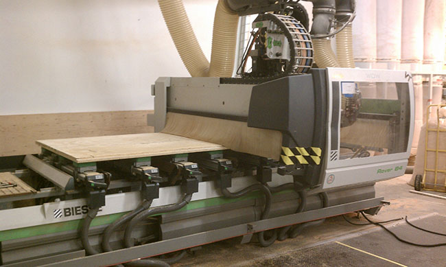
After many design iterations, it finally sunk in that we actually had to build something. We made arrangements for a robot to fabricate all of our plywood components directly, using files from our 3D computer model. To make it a little more interesting, we thought we would try and integrate a hand-made, rough-hewn, hemlock chassis that was fabricated in a separate facility.
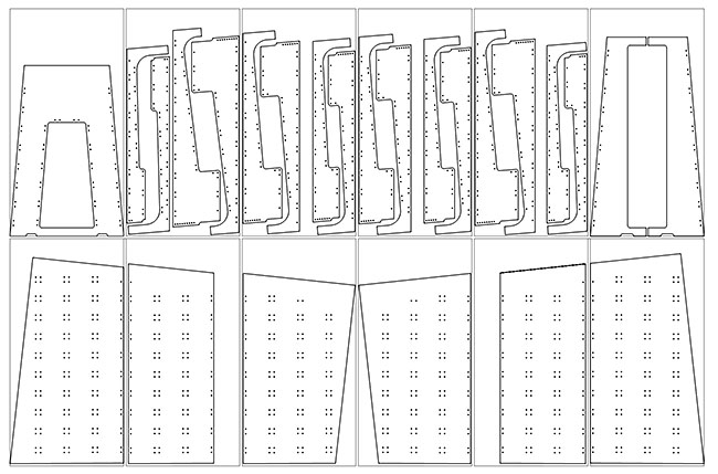
Our first step was to make all of the individual parts that would eventually come together to form the shanty. We used two separate fabrication methods. The first was initiated by emailing a file to Walker Office Works that contained 1:1 scale drawings of each plywood panel profile for the shanty. We have worked with Walker Office Works on custom furniture in the past, and they were gracious enough to let us come see their process.
Before seeing how this ‘sausage’ is made, I would have thought that one simply opened a file, ‘pressed play’, and the machine would perfectly and effortlessly produce exactly what you tell it every time. This was not the case.
First, each sheet of plywood needs to be loaded and secured to the machine. The machine operator then must tell the machine what type and what size tools to use and precisely program a path for the tools, telling them what speed, direction and on which side of the line to cut. If all goes as planned, the machine will chug along and spit out life-size copies of the drawings.
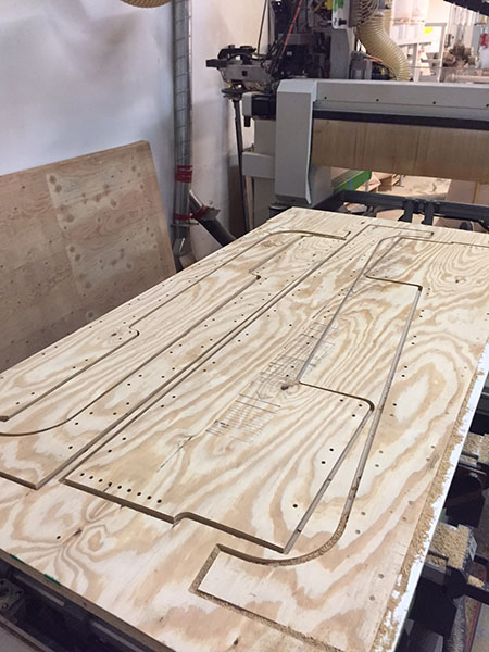
However, there are two phenomena that conspire to ensure that plans will be foiled periodically. One, which is normally a benefit, is that it will cut exactly what is drawn, so the drawing must be extremely accurate. The other pitfall is that the machine will continue to follow its marching orders even when conditions change, like when the panel shifts or an overworked tool begins to chew up the plywood. Thankfully, we suffered only a few of these learning opportunities.
The final step in fabricating the plywood components was performing the arduous and thankless process of sanding and staining each panel.
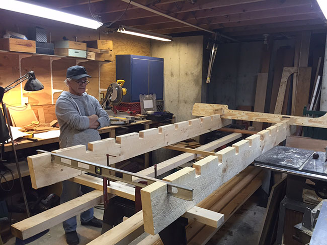
While the robot, or CNC machine, cut the plywood, Mr. Kielman, our self-proclaimed wood gnome, whittled away in his cave on a hemlock chassis to which all of our panels would be fastened. Similar to our CNC fabrication line, measurements were taken directly from the 3D model. But in this case, they were written in a list on paper.
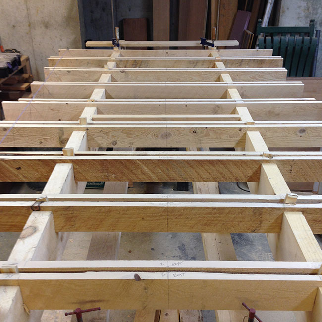
Another distinction is that our wood gnome is not a robot, so he could adapt his technique to situations as they developed, which proved useful in mating the two systems later. 2×10 rough sawn hemlock boards were used as the main rails. These rails were then notched to accept pairs of 1×6 joists that would hold the plywood ribs. It was then time to bring all of the pieces to the assembly line.
ASSEMBLY:
Building a full-scale structure is a little outside our typical scope of work, so we were lacking critical workspace. Thankfully, our friends at Burlington City Arts graciously offered us some garage space on Pine Street to assemble our shanty.
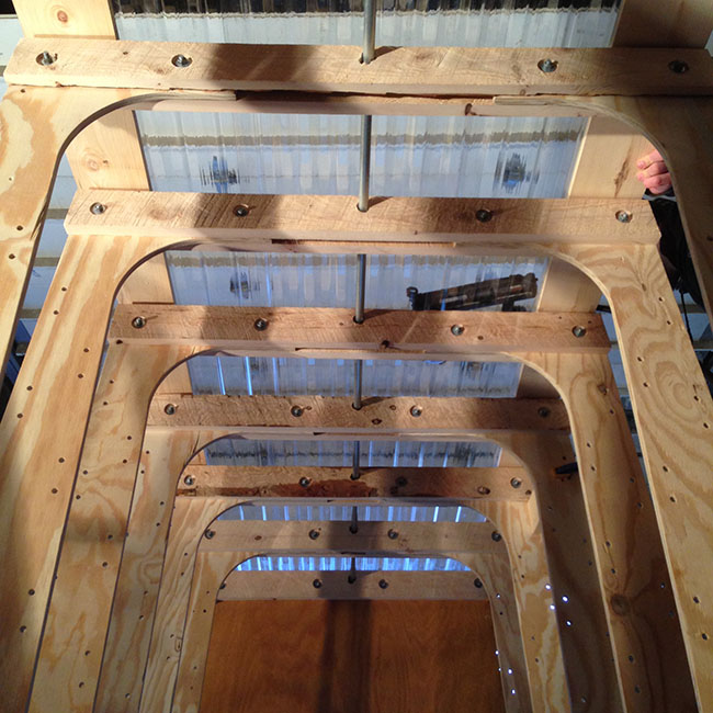
Our first task was to bolt together our plywood/hemlock hybrid structural bents and fasten those to our rails.
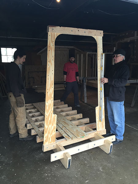
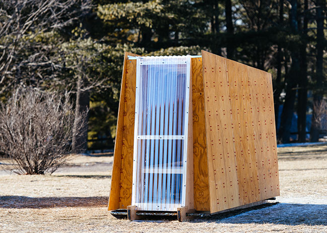
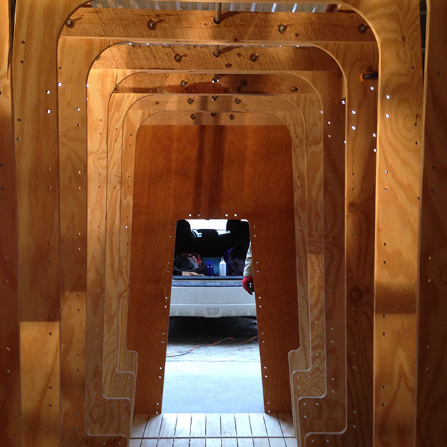
Once the structure was in place, excitement grew as the overall form and details came into view. The slightly modulating ribs implied the walls, roof and bench yet to be installed.
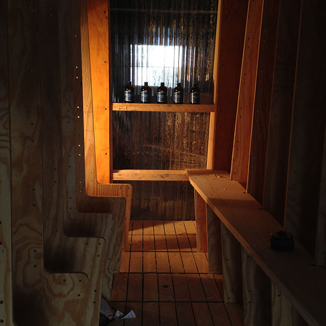
A steel rod pierced through the center of the upper ribs which, along with integral tie-offs in the ribs, would allow fishing line to be held and reeled out of the way or wherever it’s needed.
Floor boards were installed with integral, concealed hatches, operated by a small round finger pull that would provide access to the ice and cold storage.
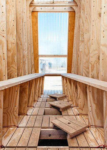
Next, the window needed to be installed. Our ‘window’ was a continuous band of clear, corrugated plastic, occupying the entirety of one wall and the roof.
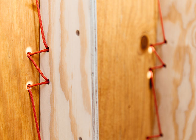
This window was a much-needed connection to the outdoors, providing views and passive solar gain. The final assembly task was to fasten the plywood wall panels to the ribs. We chose to do this by laboriously lacing them together with red, nylon paracord. The detail references nomadic, hunter/gather culture, and it provides a subtle and tasteful splash of color.
COMMISSIONING:
Once construction was substantially complete, the shanty needed to undergo testing to ensure that certain design criteria were met.
First, the aesthetics test; did it look like we intended? It did. There it sat, its deceptively simple form at once hovering, shifting and leaning in different directions.
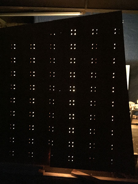
Next, the lighting systems test. The lace holes on the panels were meant to display a pixelated representation of the activity within … check.
Then, the plumbing systems test. The integral floor hatches provide access to fresh water and are sized to stash a six-pack while a custom carved shelf holds one’s current beverage … check.
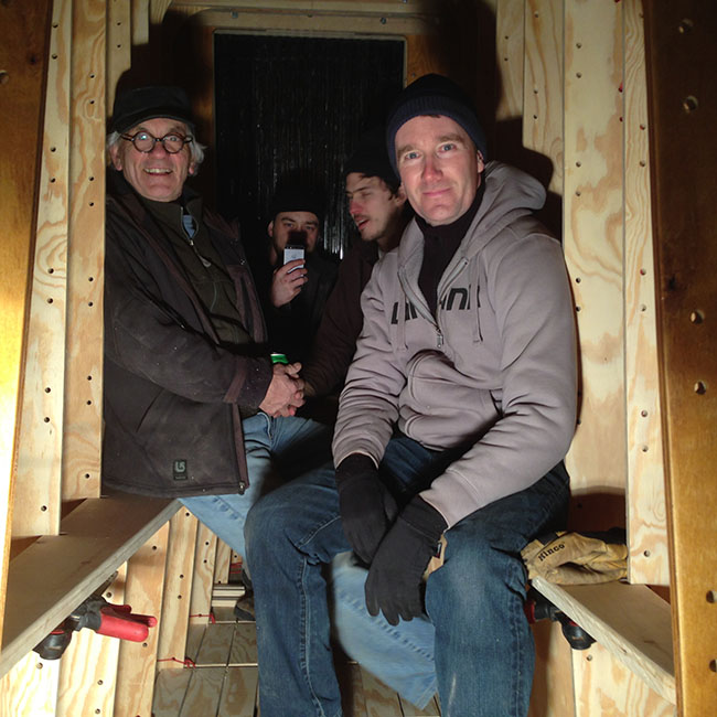
Finally, the thermal / air quality testing. During the design phase there was much deliberation over whether to insulate or not. As soon as more than two people occupied the space, it was clear that, despite the hundreds of holes in the walls, it was still comfortably warm and provided much needed ventilation. …check.
Having successfully completed our extensive battery of tests, the shanty was ready to leave the shop and join its fellow shanties on the museum grounds.
DELIVERY:
Our final challenge was getting our shanty out of the bottle it was built in and onto the trailer that would carry it to the museum. It was very tight on both fronts, but the crew from Shelburne Museum was great and everything went smoothly.
Finally, it was time for us to leave our humble facility and our friendly neighbor, John Marius at Champlain Metals. John provided several essential metal fittings and accessories that completed the project. Before we left, Mr. Marius sent us off with: pipe axles for towing/winching, a door threshold/boot scraper, blades for the wood rails, and the piece de resistance, a giant, rusty fish hook that sat in his shop for a decade waiting to adorn the head of our faux-fur door-flap.
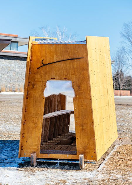
The shanty proudly sat on the museum grounds for 5 months before summering at the BTV airport baggage carousel, but it has yet to see its natural habitat or experience its intended use. Maybe this winter our shanty will find a nice spot on the lake where some lucky angler will finally bring it to life.